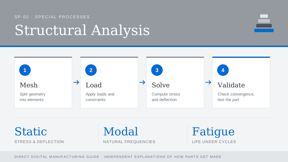
Structural analysis predicts how a part will respond to loads before anything is built. The standard tool is finite element analysis (FEA): the geometry is divided into a mesh of small elements, material properties and boundary conditions are applied, and a solver calculates stresses, strains and deflections across the part. Packages range from tools built into CAD to dedicated solvers such as Abaqus, ANSYS and Nastran.
Types of analysis
- Linear static: stress and deflection under steady loads; the everyday check.
- Modal: natural frequencies, to keep parts away from vibration sources.
- Fatigue: life under repeated loading, critical for aerospace and automotive parts.
- Thermal and thermo-structural: expansion and stress from temperature changes.
- Topology optimization: lets the software remove material that carries little load, often producing shapes only additive manufacturing can make.
Additive-specific caution
Printed parts are not always isotropic. FDM parts are weaker between layers, and as-built metal parts can contain porosity and residual stress. Use material data from parts made on the same process and orientation, and validate critical designs with physical tests.
Common mistakes
- Over-constraining the model so it looks stiffer than reality.
- Trusting stress peaks at sharp corners, which are often mesh artefacts.
- Skipping a mesh convergence check.